Print, video, sounds

Picosecond Pulse Labs 6110D teardown

Opening up a reference flat pulse generator shows some old-school design. pdf version
Picosecond_Pulse_Labs_6110D_pair.jpg
A local calibraion lab had a half-dozeon of these pulse generators on eBay. I bought three to hand out as party favors to my pals. What a reference flat pulse generort does is take and input pulse train, and output a pulse train that goes fron 1 volt to ground. But when it drops to ground it does so with very little ringing or undershoot. This lets you feed the siganl to amlifer circuit sto see how little ringing the amplifer has. The power and input signals come into the unit via a 5-pin mini-DIN connector. So its nice to have a wire kit to make the harness:
Picosecond-Pulse-Labs_6110D_02.jpg
Bottom of first columnmove down to the left

Picosecond-Pulse-Labs_6110D_03.jp

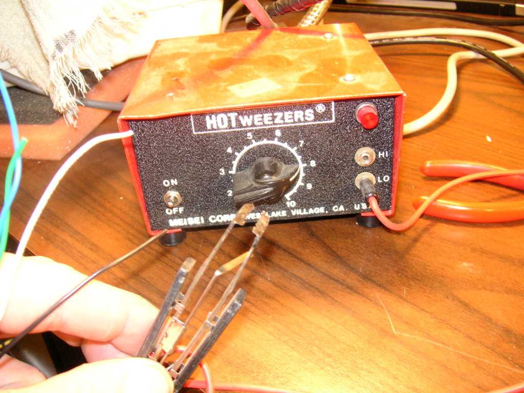
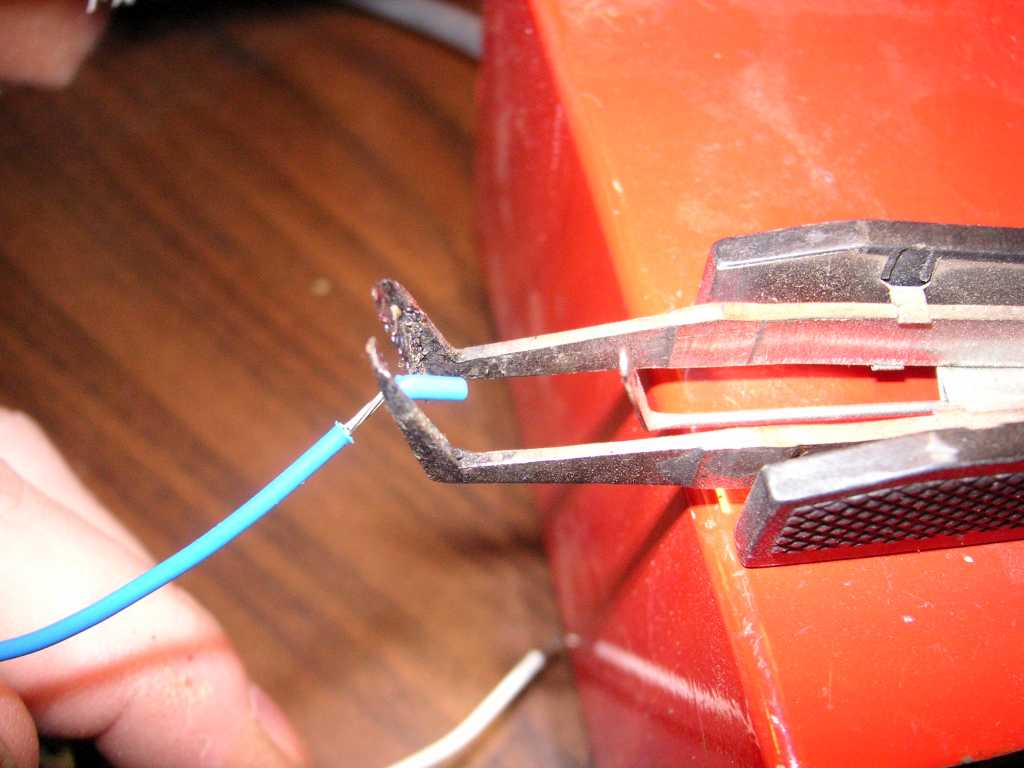
Stripping wire is a delight with the HOTweezers thermal wire stripper. I got two in the local salvage yards.
Picosecond-Pulse-Labs_6110D_04.jpg

Thermal strippers melt the insulation and will not nick the copper wire. I first saw them used in at a military contractor that made satellites and jet avionics.
Picosecond-Pulse-Labs_6110D_01.jpg
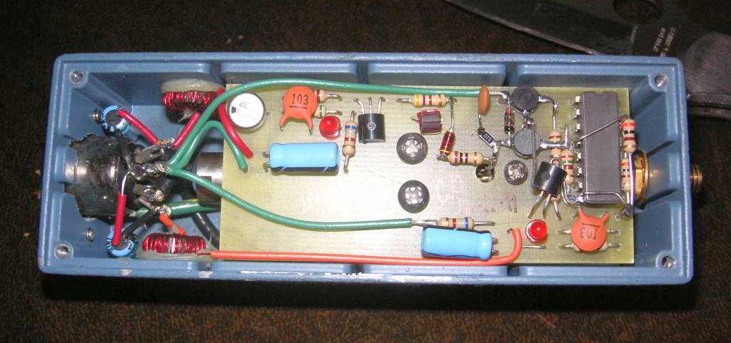
Opening the cover shows a mix of point-to-point wiring a a PCB (printed circuit board).
move up a little to the right move down to the left
Picosecond-Pulse-Labs_6110D_05.jp
The output is an SMA connector as befits a high-speed pulse. The pulses are slow, but with sharp edges, the Fourier components are fast.
Picosecond-Pulse-Labs_6110D_06.jpg
Fitting the mini-DIN input connector.
Picosecond-Pulse-Labs_6110D_07.jpg
A fully-equipped lab evaluates the modules.
move up a little to the right move down to the left
Picosecond-Pulse-Labs_6110D_08.jpg
A machinists headband magnifier helps you see the parts.
Picosecond-Pulse-Labs_6110D_09.jpg
The scope is triggered by input pulse generator.
Picosecond-Pulse-Labs_6110D_10.jpg
This HP 8082A pulse generator feeds the Picosecond pulse generator.
move up a little to the right move down to the left
Picosecond-Pulse-Labs_6110D_11.jpg
The first unit works fine.
Picosecond-Pulse-Labs_6110D_12.jpg
The second unit also works.
Picosecond-Pulse-Labs_6110D_13.jpg
The third unit is bad, the waveform is not tightly driven.
move up a little to the right move down to the left
Picosecond-Pulse-Labs_6110D_14.jpg
.
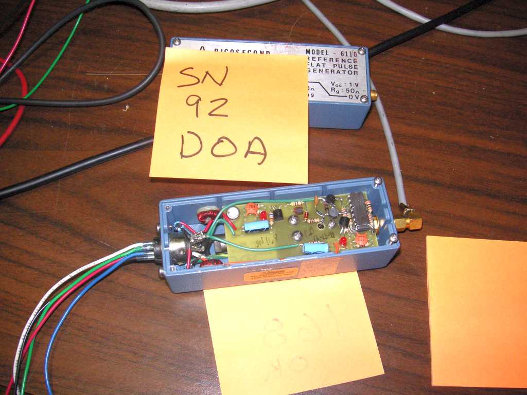
Here is a good one opened up, with the bad unit right above it.

You can see the SMA cable from the unit to the scope. I have sinse stopped using right-anlge SMA cables, since they usualy have more impednce anomiliew that a simple straight cable.


Files
move up a little to the right move down to the left

This post is in these categories:

border bar
Bottom of first column This is the end.