| Print, video, sounds |
|
 Engineering disaster: the Ford ignition
|
 | |||||
  |
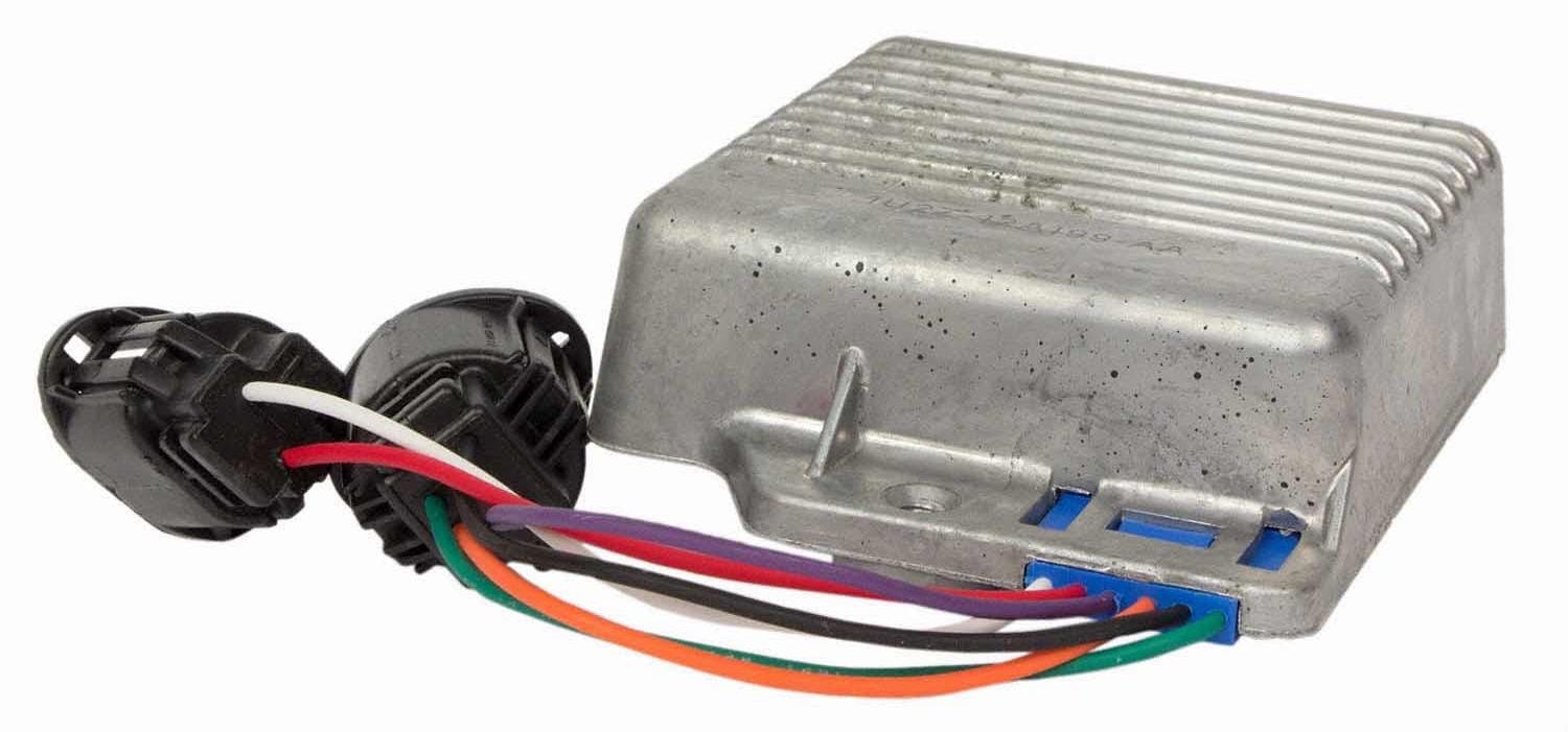 In addition to the packaging in the engine compartment, the module also had pigtails, something discussed in our wiper motor disaster article. It was the same problem. Assembly workers could carry six or eight modules by the wire pigtails. This would break the wires and cause failure at the end of the assembly line. The wire pigtails also had a rattle problem. You have to secure those connectors so they don't make noise when you drive over rough roads. 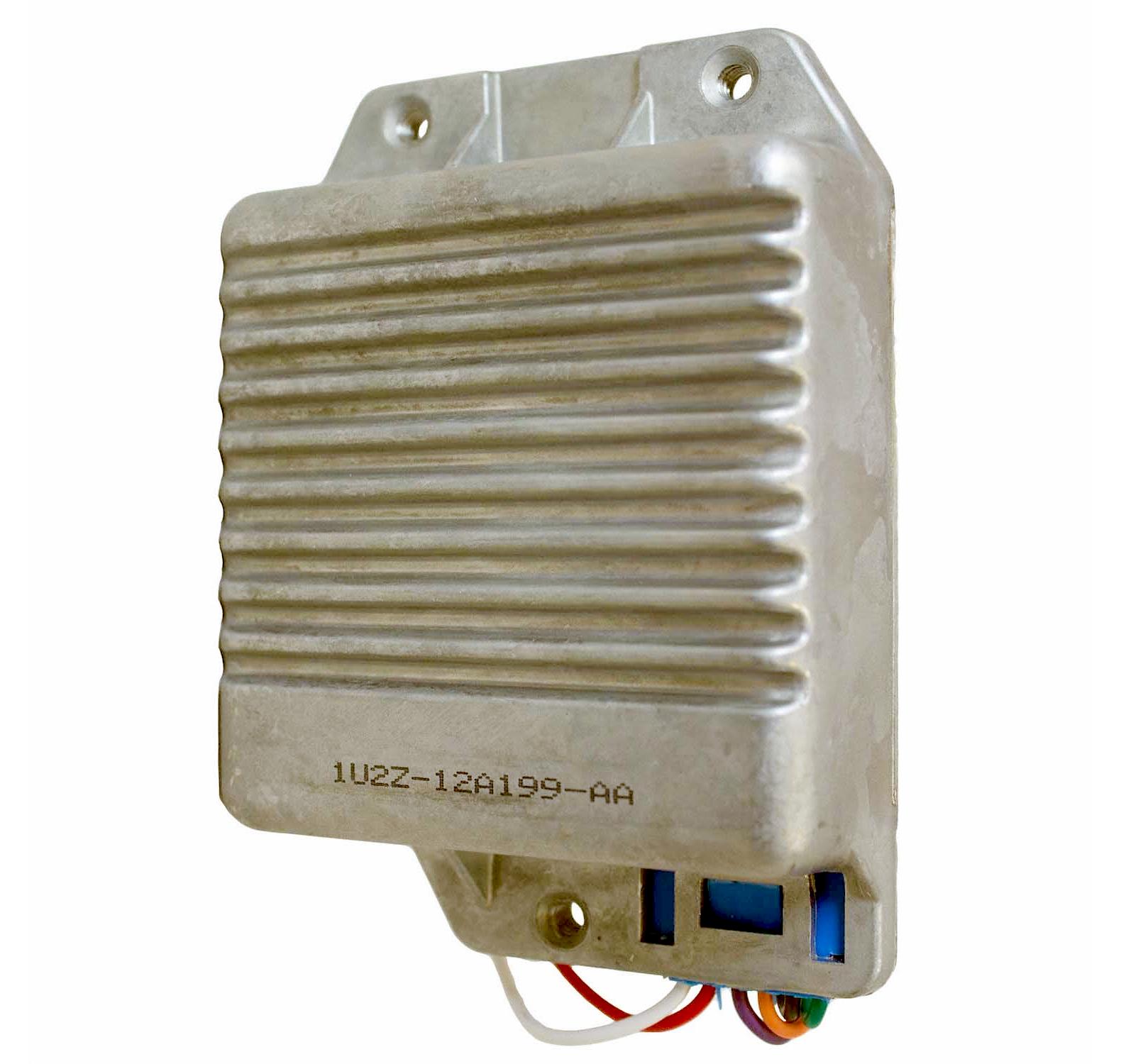 This is a genuine Motorcraft Ford service part. You can see the part number starts 1U2Z. A handy Ford part number decoder shows 1= 2001 release year, U2= Motorcraft Brand, and Z= Ford Customer Service Division Product Analysis / Ford Service Parts. This is a part number cut after 1999. When I worked on the truck, the part number started E0TB, E0= 1980, T= Truck, and B meant Body and Electrical Products Engineering (BEPE) release authority. |
 |
  |
 This is where the problem started. The circuit board was potted in the module with an epoxy filler. This caused the circuit board to crack when the module experienced temperature cycling under the hood. It was an insidious failure mode. Drivers would coast to the side of the road, open the hood, and poke around. This let the module cool, and broken circuit board traces would re-connect. Then the driver, clueless about what was going on, would get back in the car and it would start. Years later I met a tech that got stranded. He knew it was the module, so he unscrewed it and put a "drunk bump" he found nearby under the module. He screwed it down and it worked for five years. 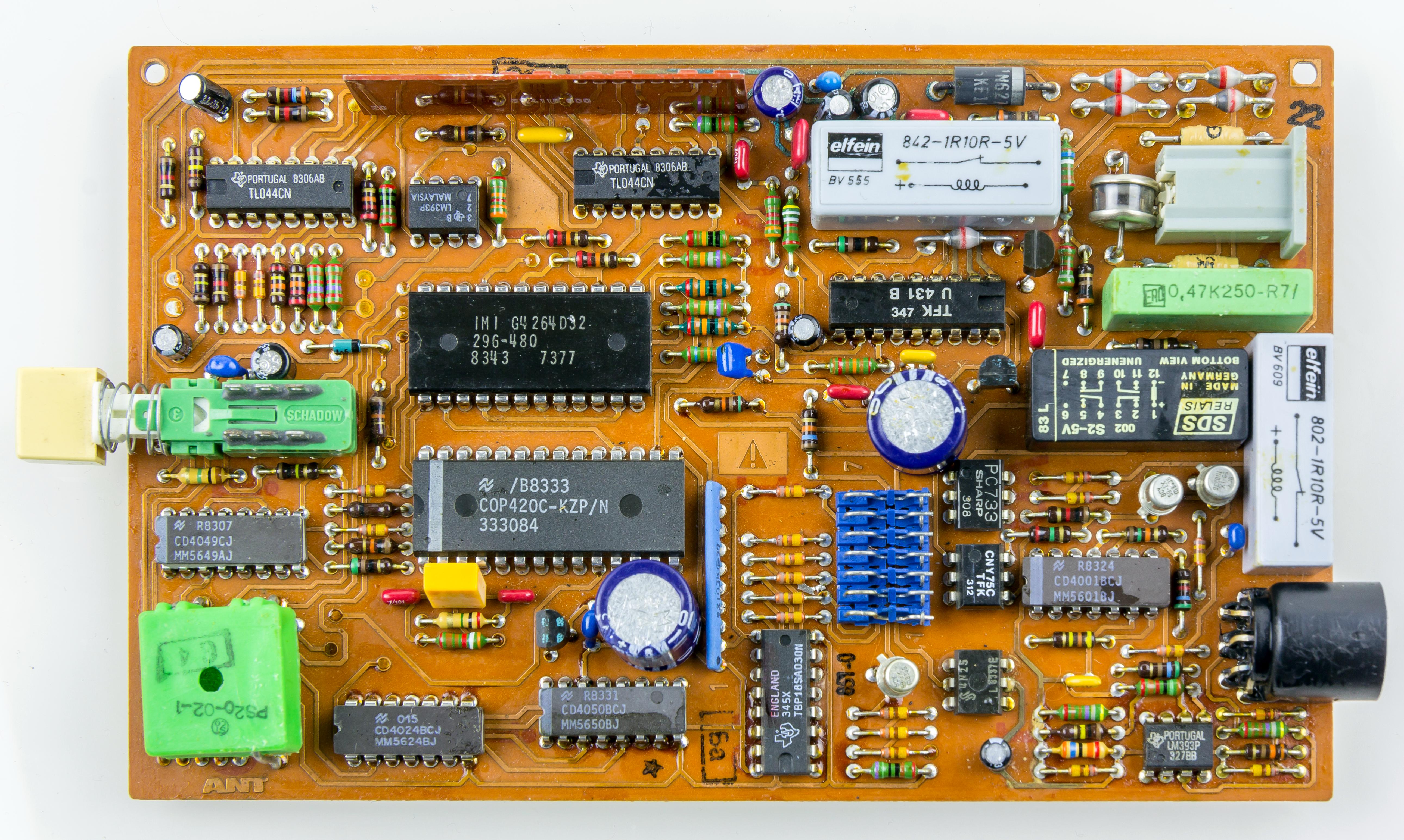 This is an example of a paper-phenolic circuit board. It is made from layers of paper glued together with thermoset phenolic plastic. You can often see them inside appliances and older cheap consumer electronics. |
 |
  |
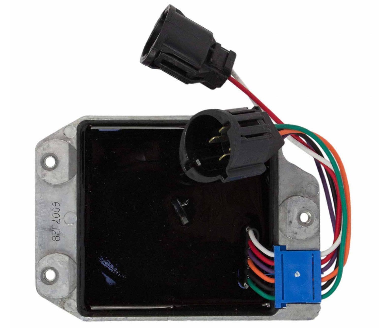
When the module heated up, from engine temperature and its own internal heating, the paper phenolic circuit board cracked. That killed the car. 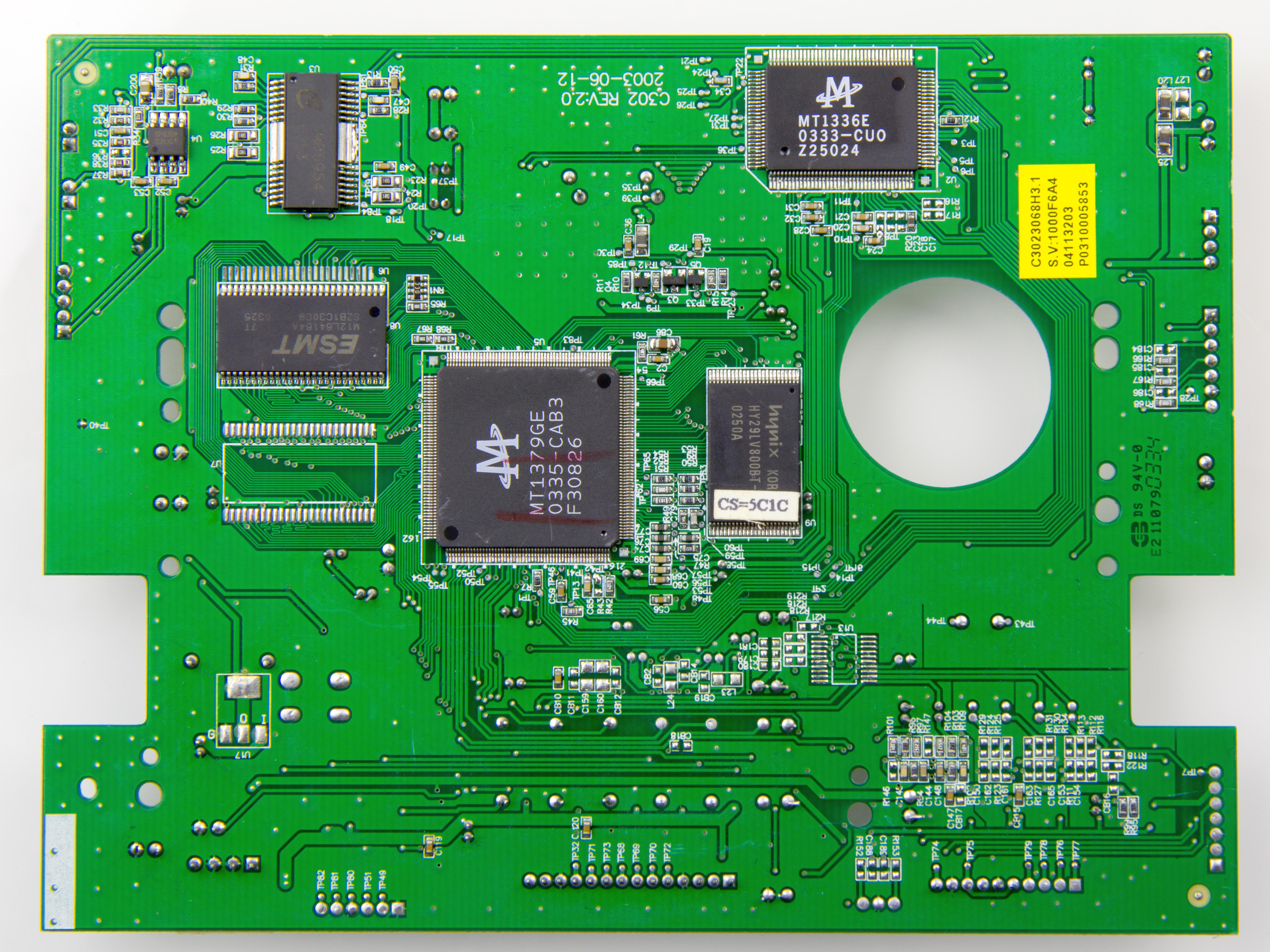 I said no problem, just replace it with an FR-4 board. That is a fiberglass epoxy construction. FR does not mean fiberglass reinforced, it means "flame resistant". With no paper content, these boards would not burn, but they were also much stronger. Management looked at me like I was insane, FR-4 boards would be almost a dollar penalty, times six-million vehicles a year. Instead, the fix was to pour nice cheap sand into the housing, lay the board on top, then pot it in. Since sand is cheaper than potting, I think they could book it as a costs saving. 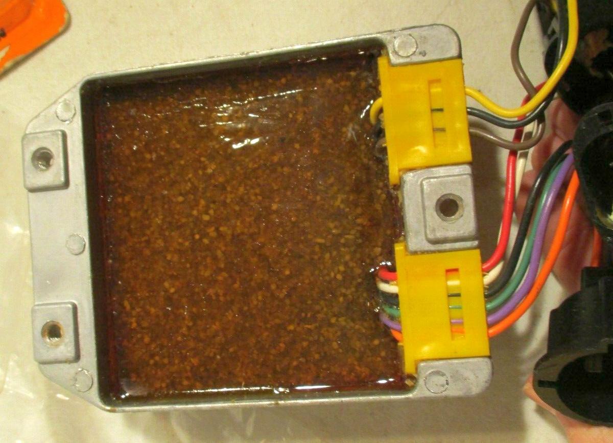 This is an aftermarket module, but you can almost see the sand underneath the potting. |
 |
  |
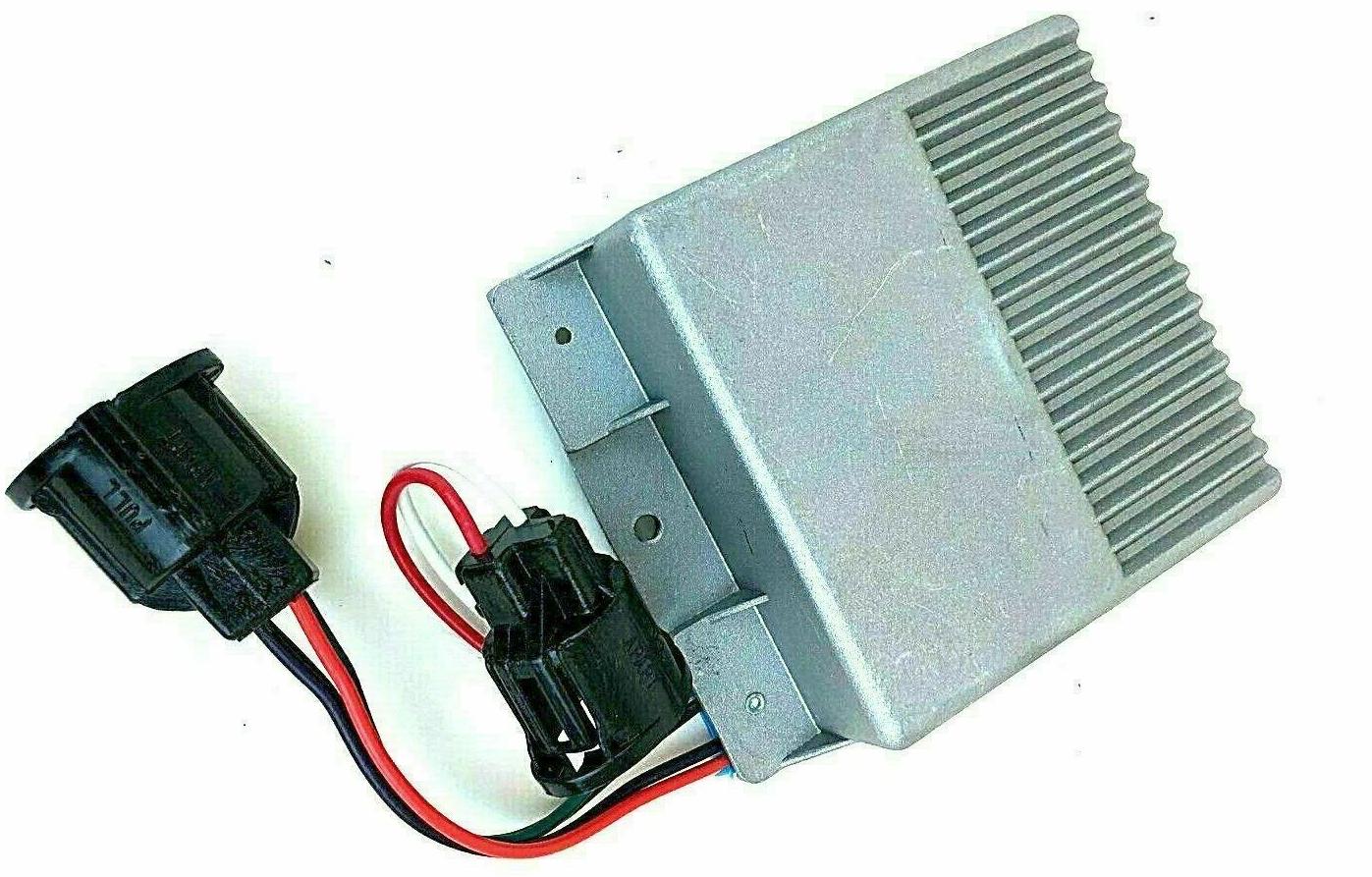 This is another aftermarket ignition module. They put fins where the high-current transistors are, and left the module smooth elsewhere. Pretty smart. When under the hood, the fins transfers heat out, but the cooler part of the module is smooth, minimizing heat transfer in. This is another aftermarket ignition module. They put fins where the high-current transistors are, and left the module smooth elsewhere. Pretty smart. When under the hood, the fins transfers heat out, but the cooler part of the module is smooth, minimizing heat transfer in.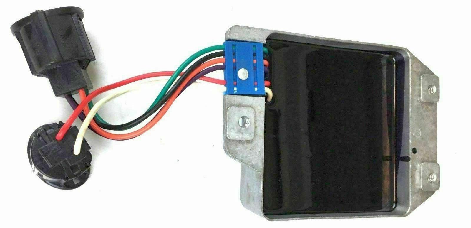 The underside of the aftermarket module shows the black potting compound. Decades later I worked at Teledyne on high-voltage power supplies for aircraft radar tubes. They vacuum-potted a lot of electronic assemblies. It was there I learned that a hard potting compound transfers heat better. Yet it will also rip components apart when they temperature cycle. One tech told me he could fail anything with a few -55°C to 125°C temperature shock cycles. A flexible rubbery potting compound will keep things from breaking, but it is much worse at transferring the heat out. So it is a delicate balance, designing the component heat characteristics, and selecting a potting compound and housing that will keep temperatures down but not be so stiff it will also break thinks inside the potting. |
 |
  |
This post is in these categories: |  |
  |