| Print, video, sounds |
|
|
lower electric power bills and just as
importantly, less heat rejected into the system. Reducing heat rejection and power consumption will create a cascading set of results that provide both lower initial costs and lower operations costs. The combination of the two provides the lowest total cost of ownership (TCO). In older cell phone modulation schemes linearity of the output stage was not important since the demodulation was not dependent on linearly. Signals such as CW, FM, and GMSK (used in GSM) have a constant envelope and do not require linear amplification. New modulation schemes such as EDGE require very linear amplifiers in order to work properly. This linearity can be achieved by not driving the RF amplifier as hard, leaving head-room between the output signal and the power supply voltage. The problem with this is that doing so directly harms the efficiency of the amplifier. Efficiency in single-transistor output stages improves as the output swing approaches the power supply rails. If the circuit designer can chose power supply voltages and load impedances so that the output stage swings close the rails then the efficiency will be improved. Average power dissipated in the output transistors is less because the output transistor will have less voltage across it as the output signal nears the power rail. Unfortunately, driving the output signal closer to the supply rail will also reduce the linearity of the amplifier. This is just as true at RF frequencies as it is at audio frequencies. Any amplifier will have less linearity if the circuit design causes it to swing to values very near the power supply rails. The ultimate expression of linearity problems in an amplifier is when the amplifier clips, and there is not enough power supply voltage to allow the signal excursion to properly represent the amplified input signal (figure 1). |
 |
  |
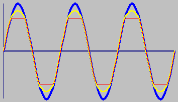 Figure 1; Clipping distortion is apparent when comparing the blue input to the yellow moderately clipped output waveform or the red hard hard clipped output waveform. Symmetrical clipping like this shows up as odd harmonics in the frequency domain. Amplifier non-linearity creates intermodulation distortion that is not harmonically related to the two input tones. The need for linearityIt may not be immediately apparent to you, but for many RF systems linearity is not very important. The fact that designers use class-C amplifiers should suggest that a perfect representation of the input sine wave might not be critical to the communications requirements of some types of signals.Imagine the RF signal from an FM radio station. In FM transmissions, all the information in the signal is contained in the zero crossings of the waveform. If the peaks of the waveform is "squished" or distorted there need be no degradation in the fidelity of the demodulated signal. Over-driven FM radio signals will create frequency harmonics of the carrier frequency and those harmonics may be objectionable from an interference standpoint, but a receiver tuned to an over-driven FM radio signal will still operate successfully (figure 2). |
 |
  |
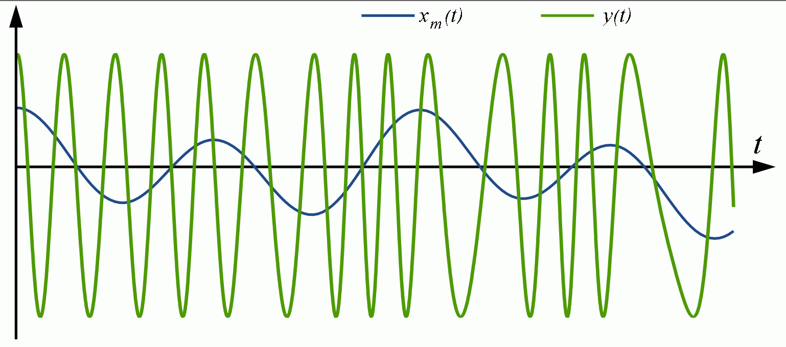 Figure 2; The frequency modulated signal y(t) is immune to amplifier non-linearity. The information is contained in the zero-crossings, not the amplitude, so that amplitude distortion in the amplifier does not cause problems. Over the past decade the acquisition costs and revenue demands of cell phone radio bands have encouraged advance modulation schemes that allow for more information to be passed in a narrower frequency band. A figure of merit relating this is called bandwidth efficiency and it is expressed in mega-bits per megahertz, or as bits per second hz. The information carried by modern and proposed cell phone standards such as EDGE is contained in far more than the zero-crossings of the signal. The new cell phone modulation schemes such as QAM (quadrature amplitude modulation) carry information in both the phase and amplitude of the envelope signal imposed on the RF carrier frequency. Examine the classic QAM-64 vector constellation (figure 3). |
 |
  |
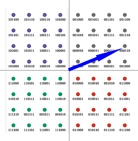 Figure 3; A QAM-64 constellation can encode 6 bits per symbol vector. Some vectors will be more subject to phase errors and some vectors will be more sensitive to amplitude errors. In either case the accuracy of the waveform envelope critical, which is why the amplifier linearity is so important. Figure 3; A QAM-64 constellation can encode 6 bits per symbol vector. Some vectors will be more subject to phase errors and some vectors will be more sensitive to amplitude errors. In either case the accuracy of the waveform envelope critical, which is why the amplifier linearity is so important.The envelope of the RF signal is created by representing the phase and amplitude of the signal based on a series of symbol vectors. Since there are 64 vectors the information carried by any given vector can represent 6 bits of digital information. This is what provides the bandwidth efficiency of QAM-64 modulation schemes, which approach 6 megabits/sec per megahertz. A little thought should make apparent the problems caused by poor linearity in such an advanced modulation scheme. Since the demodulator needs an accurate depiction of both amplitude and phase of the signal, the instantaneous accuracy of the signal is important, unlike FM transmissions where it is only the zero-crossings that matter. If the |
 |
  |
|
operating signals drive the RF power amplifier close the output rail the
inherent logarithmic non-linearity of the transistor is compounded by
the fact that the transistor is approaching saturation. This means that
the symbol vector that is being encoded by an amplifier no longer has
the correct amplitude and phase. When the non-linearity is severe enough
the symbols overlap and the information is lost. You could conjecture a
demodulation scheme that would account for the inherent non-linearity
of a transistor, but the fact that the biasing of that transistor
establishes where on the logarithmic transfer function the transistor
operates would make the task very difficult. Compounding these
difficulties is the fact that the saturation of the transistor as it
approaches the power rails would be very hard to factor into to any
demodulation scheme since each RF source has a somewhat arbitrary power
supply voltage. Indeed, the only solution to poor symbol accuracy is
improving the accuracy of the RF power amplifier. The canonical class-A output stage will have inherent non-linearity due to the transistor curve. This makes the positive and negative excursions of the output signal non-symmetric. At lower frequencies this non-linearity is overcome with feedback. Transistor amplifiers soon evolved into operational amplifiers that have extraordinary forward gain. The forward gain of a modern op amp can exceed 120 dB or a million to one. By having such a large forward gain this allows the designer to improve linearity by using a large amount of negative feedback. This combined with class-AB output stages can produce linearity as remarkable as that seen on National Semiconductor's LME49710, which specifies a linearity of 0.00003%. You need to realize however that these good linearly specs are for operation at relatively low frequencies. |
 |
  |
|
All amplifiers exhibit a roll off of gain with frequency.
Current-feedback amplifier architectures have less gain loss at high
frequencies but they still will roll off at high frequencies. Remember that the linearity improvement achieved with large feedback was predicated on having a large forward gain. But since amplifiers have less and less forward gain at higher frequencies, they also are less able to have large feedback at high frequencies. This is why RF amplifiers, especially RF power amplifiers, are not able to use conventional feedback at the gigahertz and above frequencies at which they operate. Just as daunting, the open-loop nature of most RF amplifiers means that they are subject to power supply rejection and output saturation problems. Since RF amps operate near the frequency limits of the transistors themselves, they cannot practically be made into high-gain operational amplifiers. In this regard RF amplifier design is still saddled with all the difficulties faced by designers of tube equipment decades ago. In addition to the linearity problems facing all amplifier designers, there are some other linearity impediments that make RF amplifiers even more challenging. There are memory effects that introduce time or data-dependent non-linearity. These memory effects are caused by electrical and thermal operation of the amplifier. Electrical memory effects are analogous to the memory effects that you can observe in an old tube guitar amplifier. These old amps had cheap power supply systems, often an open-loop linear supply that was just a capacitor hung across a tube-rectified line voltage. If the guitarist would play a loud power-chord the |
 |
  |
|
output stage would be driven very hard and pull down the power supply
voltage as the capacitor was drained. The line voltage will restore the
capacitor after the heavy load, but it will take tens of milliseconds to
do this. The sag in the power supply voltage changes the biasing of the
output transistors in the guitar amplifier. This creates distinct
non-linearity, and those are 'data dependent" as the software engineer
might say. The degree of non-linearity depends on the previous signal. RF power amplifiers are subject to the exact same phenomena. If the sequence of data happens to require symbols that drive the amplifier hard, then the power supply and biasing of the amplifier is effected and time-dependent non-linearity is created that will change with the modulation of the RF carrier. Besides these electrical memory effects there are thermal memory effects that are familiar to designers of amplifiers. A hot transistor has a different transfer function that a cool one. Once again, this induces a time dependent non-linearity into the system. If the environment is hot or the data stream is such that it heats up the output stage, then the transistor will exhibit different non-linearity than it would at a cool temperature. As RF power amplifiers are included into CMOS chips there are sure to be even more thermal problems. Amplifier design genius Bob Widlar once had a problem with an operational amplifier that stopped working property at 1 kHz. He sat and thought about the chip layout and realized that at 1000 hz there are standing waves of heat that are propagating away from the output transistors and across the rest of the silicon die. His work on high-power amplifiers had taught him that silicon crystals are not isothermal while in operation. Indeed he had |
 |
  |
|
previously seen 25 degree C gradients across a die. In this case the
gradients were far less, but Widlar had put two reference nodes in his
amplifier and they where not located the same distance from the output
transistor array. At 1000 Hz one of the nodes was in a temperature peak and the other was a temperature minimum. This caused the amplifier to behave erratically. In this case we can see thermal memory effects that are dependent on time, power output and frequency of operation. An RF amplifier that does not have the benefit of large feedback factors will exhibit changes in linearity based on all these thermal effects. In summary, the non-linearly of RF power stages is shown in figure 4. 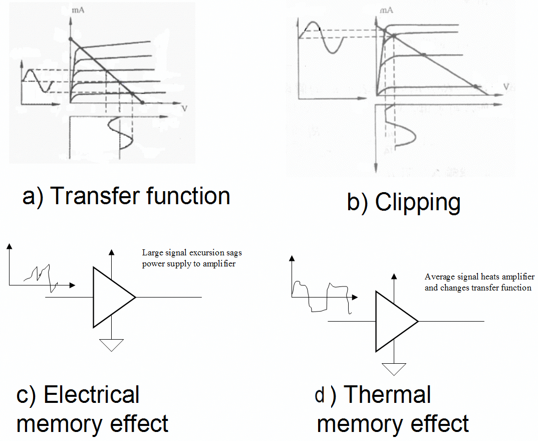 Figure 4; RF power amplifier non-linearity is due to the inherent non-linearity of a transistor amplifier (a), clipping distortion (b), and both electrical (c) and thermal (d) memory effects. At the core of transistor non-linearity is the fact that the I-V transfer function of a transistor is a logarithmic curve, not a straight line. The next issue is the saturation of the transistor as it approaches the power supply rail. Then there are the electrical memory effects that link |
 |
  |
|
power supply rejection to non-linearity. Finally there are the thermal memory effects that we have just discussed. Linearity solutionsSince the need for efficiency is paramount in RF amplifiers, the most basic linearity improvement is not available. RF designers cannot just swing the output of the amplifier across a smaller range and suffer with the efficiency hit. The practical solutions that improve linearity for these new modulation schemes, while preserving efficiency for battery life and power savings are detailed in table 1.
Since RF power amplifiers operate at such high frequencies the use of conventional feedback techniques is impractical. In this context the term feedback often refers to Cartesian feedback. In this scheme the RF signal is not fed back, but rather, the RF output is converted back down to base band and the I (index or amplitude) and Q (phase) signals are derived and that is what is fed back to the input stages. This system can achieve good linearity but some of that is predicated on not driving the output stage too hard. The efficiency is not as good as you would hope for. Since feedback amplifiers are subject to oscillation, this technique cannot be used on wideband amplifiers. Feed-forward techniques can be applied to wide bandwidths. These systems are very complex. The input and output spectrums of the signal are compared by circuitry that corrects the errors after the amplification. This scheme |
 | ||||||||||||||||
  |
|
offers good linearity but the efficiency is worse that the feed-forward technique. In order to get both acceptable linearity and good bandwidth RF designers have resorted to pre-distortion techniques. In this method the deterministic non-linearity of the system can be compensated for in the digital synthesis of the I and Q signals that do the modulation. Since a digital system can also use complex algorithms to try and predict the thermal and electrical memory effects, these setups preserve linearity in the face of these problems as well. It should be noted that the inherent linearity of the components in the RF signal path are still relevant. There is a limit to the corrections that can be provided for in the digital domain and the closer the signal path is to ideal the easier job the digital system designer will have providing an accurate pre-distorted signal. James Wong, high frequency marketing manger at Linear Technology, points out that designers are always cognizant of the inherent linearity of system components. "By providing an active up-converter with built-in amplification, combined with its noise, linearity and superior isolation, result in a superior dynamic range and minimalist solution compared to a passive up-converter followed by an amplifier. This greatly reduces the challenge presented to the digital designers that are providing pre-distortion to the signals." Indeed, Wong points out that modern base stations do use Cartesian feedback as well. Circuitry down-converts and extracts the I and Q components of the output and then feed that back to the DSP core. This allows the system to utilize extremely sophisticated algorithms that use real-time Cartesian feedback as well as pre-distortion based on the specific components used in the signal chain (figure 5). |
 |
  |
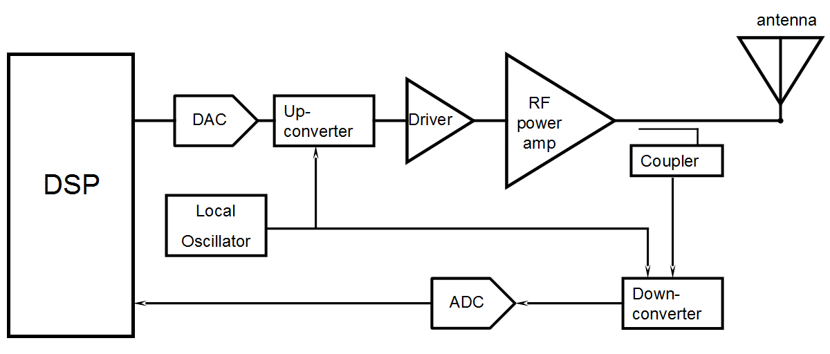 Figure 5; A cell phone base station uses digital pre-distortion based on the components that are used. Cartesian feedback also allows dynamic algorithms that can help compensate for memory effect and other non-linearity. Hardware designers should not despair that so much linearity improvement is attained with digital pre-distortion. There is always a place for hardware that improves linearity and efficiency since the better the inherent linearity the less the digital systems need correct. One architecture that is being used deserves consideration due to the insights it can give to amplifier design. This is the Doherty amplifier, invented by William H. Doherty of Bell Laboratories in 1936 (figure 6, reference 1). 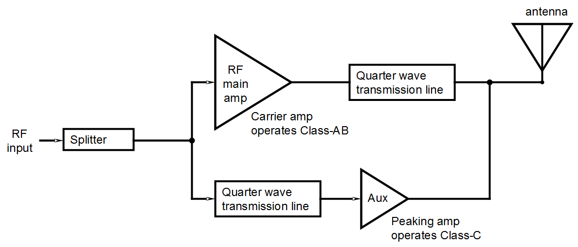 Figure 6; The Doherty RF amplifier achieves better efficiency by using an auxiliary amplifier to vary the load impedance on the primary amplifier. This allows the primary amplifier to be kept swinging a large signal which dissipates less power in the amplifier. If the auxiliary amp lowers the load impedance on the primary amplifier it will deliver more power. |  |
  |
|
In this amplifier there are two RF paths. What you should notice is
that the RF is not just shuttled between a low-power and high power
stage. One way to look at the demands of efficiency in an RF amplifier
is to realize that the output voltage swing should be large relative to
the power supply rails. What the Doherty amplifier does is use the second amplifier to change the apparent output impedance on the main amplifier. If you look at figure 7 you can see how an amplifier feeding a transmission line can be said to be facing an infinite output impedance if the second amplifier produces an identical signal on the other end of the line. 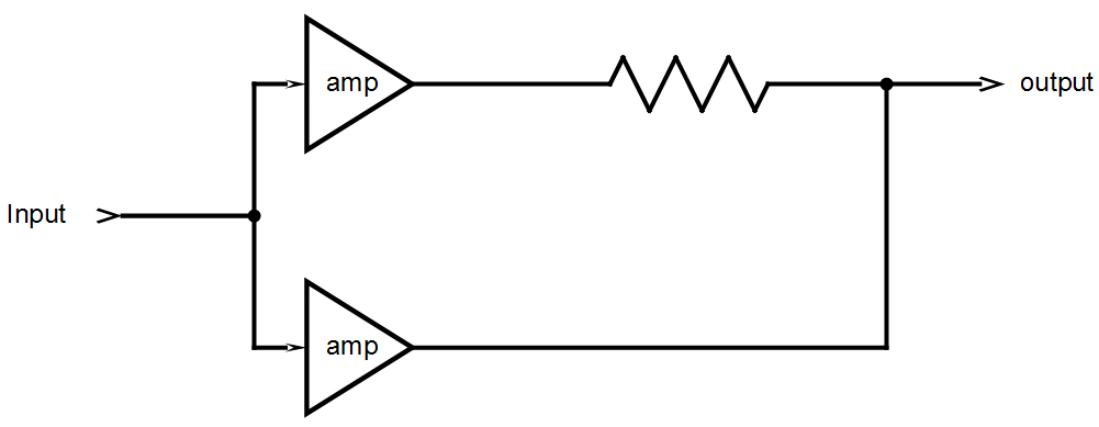 Figure 7; This diagram may make the operation of the Doherty amplifier more clear. It is obvious that is the same signal is passed to both sides of a resistor the upper amplifier will see an infinite load. Both sides of the resistor are driven at the same amplitude so neither amplifier will source any current or deliver power to the resistor. If the signal to each amplifiers are 180 degrees out of phase the perceived load by each amplifier would be twice the resistor value. A Doherty amplifier uses this principle to vary output power while maintaining efficiency. Since both ends of the transmission line are equipotential no current flows and no power is delivered. If the secondary amplifier is not driven at all then the output impedance that the first amplifier looks into is the characteristic impedance of the transmission line. By extension of this principle, if the secondary |
 |
  |
|
amplifier is driven 180 degrees out of phase of the first then the
right side of the transmission line is being driven differentially
compared to the primary amplifier and the apparent output impedance that
the first amplifier looks into is reduced to half the characteristic
line impedance. This will increase the power delivered. The main amplifier is always swinging near the output rails. If low power transmission is needed the secondary amplifier is used to increase the apparent output impedance that the main amplifier looks into. This means that for a given voltage swing near the rail, less current is delivered and hence, less power is delivered. The clever sophistication of the Doherty amplifier is well suited to the base station side of the cell phone world. On the handset side, space and cost constraints are far more severe. In this case RF switches can be used to switch gain blocks as needed. This provides for substantial power savings. Avago has develop their CoolPAM RF modules in order to allow the cell phone designers a way to maintain efficiency over wide output power levels (figure 8). 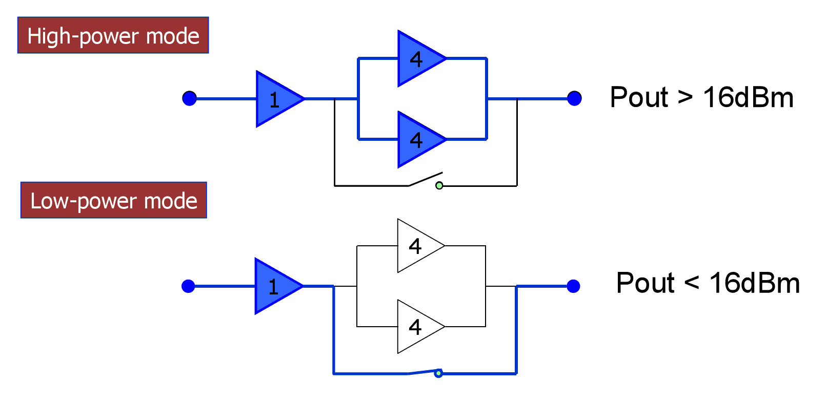 Figure 8; The low cost of handsets encourage the use of straightforward methods to improve efficiency. Avago makes amplifier modules that switch between low power and high power modes. The improvement in efficiency can add an hour of talk time (courtesy Avago). |
 |
  |
|
This straightforward technique can be used instead of feeding the output
stage with a dc-to-dc converter. Using the converters will allow the RF
output stage to always run need saturation and hence improve
efficiency, but those dc-to-dc converters consume more space and have
efficiency limitations of their own. Using their CoolPAM technology
Avago claims that talk-time can be increased over an hour, a very
compelling opportunity for cell phone designers. The trouble with modelingThe quest for linearity with efficiency in RF power amplifiers is also having an effect on the EDA tools needed to develop RF systems. It should be noted that these RF systems are inherently non-linear and hence share all the mathematical problems of other non-linear systems.Using SPICE and other circuit simulation techniques may not be applicable and may tale an extraordinary time since RF designers are often concerned with the steady-state operation of the system, a condition that may take billions of signal excursions to achieve. RF designers have typically resorted to black-box modeling techniques such as S-parameters to design systems. S-parameters do not account for non-linearity and the bias points of the amplifier are also not modeled. To solve this problem, Agilent, the company that popularized S-parameter design, has introduced X-parameters, also called polyharmonic distortion modeling (reference 2). These parameters are a combination of the response of a linear system along with the response due to the non-linear factors. Agilent has provided several papers detailing this |
 |
  |
|
technique and the inclusion of x-parameter simulation in Agilent's RF
design tools and the development of Agilent's test equipment that can
characterize x-parameters is sure to follow. ConclusionThe design of RF power amplifiers is becoming increasingly difficult due the design requirements for new cell phone modulation schemes. The RF domain has long been one associated with black magic and intuitive design conducted by experienced engineers. The demands on linearity and efficiency in these new designs only further accentuate the expertise needed to create designs that work properly. The design effort is also spreading across disciplines. The RF, analog and digital designer all contribute to the performance of the signal chain. With experienced designers given access to sophisticated tools and instruments provided by the EDA and test equipment manufactures we can all look forward to even more amazing performance gains, all at significantly lower costs. This will be good for our whole planet as we become more and more connected by the magic of our telecommunication systems.References 1 http://scholar.lib.vt.edu/theses/available/etd-05062004-152027/unrestricted/Viswanathan_Thesis.pdf 2 http://www.janverspecht.com/pdf/phd_ieeemicrowavemagazine.pdf |
 |
  |
For more informationAgilentwww.agilent.com Avago Technologies www.avagotech.com Linear Technology www.linear.com National Semiconductor www.national.com Files |
 |
  |
This post is in these categories:This post has these tags:
|  |
  |