| |
| Big projects to simple ideas |
|
Milling machine
|
 | ||||||
  |
 The design concept was to put all the control electronics in a 19-inch rack. Then we could build a spare rack to try new things. The design concept was to put all the control electronics in a 19-inch rack. Then we could build a spare rack to try new things. The original control cabinet was huge, and had a paper tape drive for programs. |
|
| |
 The rack had four enclosures, with an interface enclosure added later, and by mistake. Components that were in that cabinet could have been housed in the servo or spindle drive enclosures. The picture above does not show the rack-mount PC with a PMAC motion control card. The rack had four enclosures, with an interface enclosure added later, and by mistake. Components that were in that cabinet could have been housed in the servo or spindle drive enclosures. The picture above does not show the rack-mount PC with a PMAC motion control card. The rack had to interface with this wiring cabinet on the side of the mill. | |
| |
 In addition to the huge original control cabinet, the mill came with this gigantic "magnetics" cabinet. Both were replaced by the rack. In addition to the huge original control cabinet, the mill came with this gigantic "magnetics" cabinet. Both were replaced by the rack. | |
| |
 The Delta Tau operator panel needed these two cards as well.  The Delta-Tau panel was industrial quality.  A picture from 2014, when I sold or scrapped all the hardware. |
|
| |
 This was the user-panel we designed from scratch. I had talked to machinists who hated touch-panels. They wanted real switches they could feel as they watch the tool jog down. In addition, I put in three optical encoders so you could use the CNC mill like a manual mill.  I got this far with the prototype. I glued plots of the layout onto a purchased cabinet, and used that to drill all the holes. I used LCD panels instead of the LEDs in the CAD drawing. All this "cool-guy" stuff was way too much to design for a small shop. At least we had the sense to give up and purchase the Delta Tau panel. |
|
| |
 That custom operator panel needed not only schematics, but a design that could interface with the PMAC control card. We upgraded that card to dual-port memory (DPM) but that only made it more work and low-level programming to realize this custom panel design. That custom operator panel needed not only schematics, but a design that could interface with the PMAC control card. We upgraded that card to dual-port memory (DPM) but that only made it more work and low-level programming to realize this custom panel design. The custom operator panel did not need a microprocessor, but it did need a multitude of latches and registers.  |
|
| |
 More latches. More latches.  . .Even more latches.  Some decoders to parallelize the pulse-wheel encoders, It was getting pretty ugly by this point. It was nice to design something that my machinist friends loved, but all this took away from the main design effort. Lesson learned-- if somebody makes an operator panel, use it, get the machine working, and then do a redesign of the panel as a follow-on project. Some decoders to parallelize the pulse-wheel encoders, It was getting pretty ugly by this point. It was nice to design something that my machinist friends loved, but all this took away from the main design effort. Lesson learned-- if somebody makes an operator panel, use it, get the machine working, and then do a redesign of the panel as a follow-on project. |
|
| |
  |
|
| |
 The PMAC card was complicated but very high-performance. It used a custom ASIC and an Analog Devices DSP chip to control 8 axis. We made two block diagrams (above) for the PMAC and the PMAC2 we upgraded to. We also made a layout drawing of the PMAC2 card below, to remind us of where all the connectors were, and what they did. The PMAC card was complicated but very high-performance. It used a custom ASIC and an Analog Devices DSP chip to control 8 axis. We made two block diagrams (above) for the PMAC and the PMAC2 we upgraded to. We also made a layout drawing of the PMAC2 card below, to remind us of where all the connectors were, and what they did. Over a 1000 pages of manuals, scary.  |
|
| |
 The ac enclosure started life as an AutoCAD 3D drawing. Using CAD tools in advanced ways was another goal of the project. Very few machine designers had adopted 3D at the time. The ac enclosure started life as an AutoCAD 3D drawing. Using CAD tools in advanced ways was another goal of the project. Very few machine designers had adopted 3D at the time..  . In addition to the step-down transformer, the cabinet had a large EMI filter. There were 3-phase breakers for the spindle and servo enclosures, as well as single-phase power for the computer, the lube pump, and the flood coolant pump. The enclosure had solid-state relays (SSR) to operate the pumps under program control. |
|
| |
 . The 3-phase transformer was a custom order from Shape Electronics. The ac enclosure also had a small transformer to power the lube and coolant pumps. The top and bottom covers of the enclosure were perforated for air flow, so convective cooling was adequate.  . .The heat sink for the two SSRs is over-designed and oriented for convective cooling. |
|
| |
 The schematic of the enclosure shows the EMO (emergency off) lockout, as well as the transformer and SSRs. While this schematic calls out Bulgin connectors, we eventually used conventional ac connectors to save money. The schematic of the enclosure shows the EMO (emergency off) lockout, as well as the transformer and SSRs. While this schematic calls out Bulgin connectors, we eventually used conventional ac connectors to save money. The ac enclosure required several wire harnesses. Since a goal of the design effort was to document everything, there are cable drawings with dimensions and a BOM.  |
|
| |
 This harness drawing is only a single wire. This harness drawing is only a single wire. Some of the internal cables in the ac enclosure were simple, like these two. With a drawing for each cable, it would be possible to build and identical enclosure without tearing apart the existing enclosure. This was in keeping with the goals of having an evolutionary deign that could be manufactured for other machines.  Even the simplest jumper wires needed a drawing, |
|
| |
  . The ac enclosure BOM (bill of material) cost was 1500 dollars back in the 1990s. All those little parts add up. Some things like the EMI filter and a transformer came from a salvage yard so did not have a valid cost to put on the BOM. Changes always happen in a design. That is why it is important to be meticulous in rattling the changes through the whole document package. I had a boss that changed the name of a product for no reason, It required 40 ECOs (engineering change orders.) That's dumb. So is not documenting real engineering changes. Only now, 20 years later, do I see there are two T1s in the master schematic. |
|
| |
 The interface enclosure had a pretty simple schematic. All it did was take a ribbon cable from the PMAC motion controller card in the PC and break it out to two accessory cards. There was also a power supply that fed the accessory cards. The interface enclosure had a pretty simple schematic. All it did was take a ribbon cable from the PMAC motion controller card in the PC and break it out to two accessory cards. There was also a power supply that fed the accessory cards..  The major point of this milling machine redesign was the enormous space savings. Taking a giant magnetics cabinet and a clunky operator cabinet and replacing it with a rack and a small portable panel the machinist could use as he hunched over the spinning tool. Seeing this much empty space in a rack enclosure should have set off alarm bells. This could have been a 2U rack, or even a 1U, but better to put this stuff into other enclosures. |
|
| |
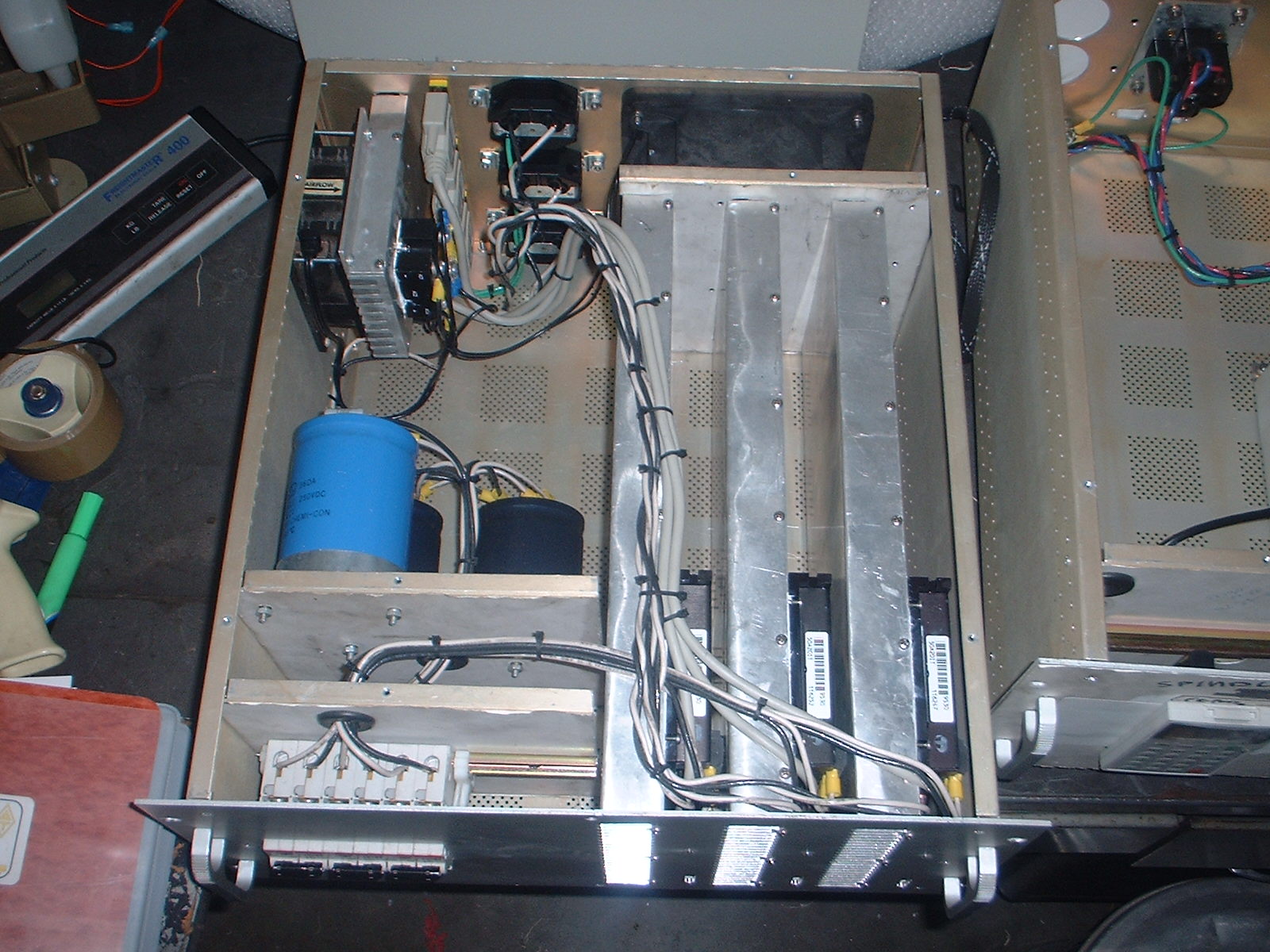
 This early CAD drawing shows the step-down transformer inside the servo enclosure. There were no heat sinks for the three amplifiers. This early CAD drawing shows the step-down transformer inside the servo enclosure. There were no heat sinks for the three amplifiers. This later AutoCAD drawing shows the servo enclosure as it was built, with large heatsinks for the amplifiers, a huge noisy fan, and a separate fan and heatsink for the rectifiers. The storage caps are behind the circuit breaker panel. it was stupid to keep the small heatsink, the rectifier could be mounted on one of the large heatsinks. So could the power supply needed by the PMAC breakout boards. As it was, we added an interface enclosure. | |
| |
 . . A SolidWorks CAD model done after the interface enclosure was added. It corrects the design and eliminates that interface enclosure. It puts the power supply and breakout cards that were in the interface enclosure into this enclosure. The rectifier and power supply are mounted on the Z-axis heatsink. It was also a mistake to have three expensive dc circuit breakers on this cabinet, as well as a circuit breaker in the ac enclosure for the servo enclosure. | |
| |
 The 2001 schematic shows the power supply for the amplifiers, as well as the cables for when there was an interface enclosure with the breakout boards for the PMAC controller. The 2001 schematic shows the power supply for the amplifiers, as well as the cables for when there was an interface enclosure with the breakout boards for the PMAC controller..  The as-built design version of the power schematic. It shows the circuit breakers, the connections to the dc MOSFET amplifiers, and the connectors on the back of the enclosure to go to the motors. After seeing that the interface enclosure could be eliminated, we drew up new schematics, showing the PMAC breakout boards inside this enclosure, also with a power supply for the breakout cards. | |
| |
 This schematic shows design intent for having the breakout boards inside this enclosure. This schematic shows design intent for having the breakout boards inside this enclosure. The ac distribution design intent.  This shows a large cable from the machine going to the breakout board for encoders etc.  . .These ribbon cables are for the operator interface panel. | |
| |
 The enclosure used a 25-pin D-sub to take all the signals from the inverter "just in case". In reality, all the inveter needed was analog speed and direction, and a fault out signal. The enclosure used a 25-pin D-sub to take all the signals from the inverter "just in case". In reality, all the inveter needed was analog speed and direction, and a fault out signal..  This is the old Vee-Arc inverter that was replaced by the inverter inside the enclosure. We sold it on eBay to offset the cost of the project. Note the brake resistors on this inverter, so the spindles would stop faster. That was planned for the new inverter as well. This is the old Vee-Arc inverter that was replaced by the inverter inside the enclosure. We sold it on eBay to offset the cost of the project. Note the brake resistors on this inverter, so the spindles would stop faster. That was planned for the new inverter as well. |
|
| |
 That large Vee-arc panel is replaced by this one inverter, but admittedly sized just for one of the spindle motors. That large Vee-arc panel is replaced by this one inverter, but admittedly sized just for one of the spindle motors. Machinists told me the three spindles made it seem like you could make three parts are once, but it was a bad idea. It was so hard to set all the tools just right, it was almost impossible to hold the close specs this machine was designed for.  A front view of the enclosure before the inverter panel got mounted on the front. It shows how much space was left over, easily enough for a second inverter if needed. The mistake of adding an extra interface enclosure rattled thought the whole design. Thankfully, this enclosure was not affected. |
|
| |
| My mentor, Big John Massa, went to Ohio State University. He said they purposely did not put in sidewalks between some new buildings. Instead, they let the students walk on the grass where
they needed to. Then, the school just put down sidewalks wherever the grass was worn away. As a guy that grew up in Cleveland, I have to love
that Ohio ingenuity. The same goes for this cabinet. With all the "guts" nailed to a sheet of plywood, I would have been able to see where the cables went. Then I would have known how to route and partition them. I would still keep the rack, but it would not be all these separate enclosures. It would have the rack-mount PC, but underneath would be one big enclosure that was hard-wired into the machine. That one big enclosure would have a regular Square-D sub-panel. I would not design a custom step-down transformer, I would just buy a standard one. Better yet, maybe a 120V dc power supply for all three servo amps.  . It is good not to build electronics onto the mill, the vibration kills things. I saw that with early Bridgeport CNCs, where the large capacitors would break out of their solder joints. |
|
| |
| I did not realize that I really needed the step-up transformer you can
see
under the old magnetics cabinet in the picture above. The spindle
motors needed 240 volts, and Silicon Valley has 208V. Motors will burn up on under-voltage, even when powered by an inverter. The inverter changes the frequency of the ac down from 60Hz. This was just simple ignorance on my part, but at least I never sold off the transformer until I scrapped the whole machine. No custom operator panel, so no need for the dual-port RAM option on the PMAC card. So then easy to mount the PMAC remotely, and use a modern PC motherboard. Using the PMAC card as an ISA-bus plug in card was a huge mistake. It meant long delicate ribbon cables had to snake out of the PC and into the enclosures. The PMAC only needed the ISA buss for power and to connect to a modem chip in the card. It worked just as well when you fed it power via a connector and instructions with a 2-wire serial cable connection. The whole point of the PMAC was to offload the PC, which you dare not depend on for timings in machine control. All the PC sent the PMAC card were short ASCII commands, very similar to G-codes. They got buffered on the PMAC, so it was a very easy, non-critical thing to "feed" the PMAC over a serial port, and no difference whatsoever to using its internal modem. Rather than buy separate power supplies for the card, we could have brought a Molex dc power connector out of the PC. That has 5V and +/- 12 volts, which would have run the PMAC2 and all the breakout cards. |
|
| |
| The ISA bus computer was obsolete even back when we designed this system
The shop was all PCI bus machines by then. We had to search for a
compatible motherboard and enclosure for an old ISA bus motherboard. To do it over, I would just lean a mid-tower PC against the plywood breadboard and use it that way until things were working. Then it would be time to look at an industrial PC, but that would be a modern-at-the-time PCI bus machine. I could see using a laptop in this day and age. Things are so non-critical with the PMAC serial port, a USB-to-serial converter cable would work just fine, and we could have upgraded the computer with no effect on the milling machine control. I would not make the EMO circuit kill the main ac power. Modern machine designers know better. Even back in 1995, I could see an axis would stop faster if commanded to stop by the amplifier, rather than have to drain all the input capacitors while things still moved. I did not brush up on my control theory. The amplifier worked in four different modes, and could take in the tachometers on the motors. It worked, but I am not sure it would have worked better with an explicit velocity loop. The servo amps had inputs for limit switches. The BostoMatic used industrial limit switches that had both a home switch, and then a limit. The home switch needed to go to the PMAC, while the limit could have gone directory to the servo amp. I now think that would be more dependable, rather than having the PMAC card shut down the amplifier. Instead, the amp would fault and PMAC could figure things out. |
|
| |
| Rather than use some handy extrusion to make giant servo amp heatsinks, I should have tried much smaller ones, convectively cooled. Perhaps the biggest mistake was mismanagement. By insisting on all those seperate enclosures, I made my employee spend most of his time making cables. He is a brilliant engineer, and I should have used him to figure out all the PMAC documentation and the PLC programming to get the machine to home and operate the lube and flood coolant pumps. It would have been much more fun for him to screw hardware to a sheet of plywood, wire it point-to-point, and start playing with the machine. We could have gone in afterwards and done all the harness drawings and cable diagrams. I also was not good about keeping the block diagrams current to the way the machine was actually getting built. This is a cardinal sin in engineering, and it shows how making cable drawings can interfere with the much more important task of overall design. Tactics should not interfere with strategy. We did do some things right. Getting the servo amplifiers with the isolated option was essential. That way the amplifier case can be connected to chassis ground and the same for the negative output of the three-phase bridge rectifier. That also meant I needed a three-phase step-down transformer that had isolation, another thing I managed to get right. We also were right not to spend 1000 dollars on a 10hp spindle drive for all three motors. Instead, we got a 3hp drive that ran a single spindle just fine. Experience is a mean teacher. It gives the test before the lesson. At least I learned the lesson. |
|
| |
This post is in these categories:This post has these tags:
Categories |  |
  |