| Big projects to simple ideas |
|
|
TOPIC NUMBER: N92-129 PROPOSAL TITLE: Articulated, Deployable Wing VTOL Aircraft FIRM NAME: Rako Electronics PHASE I or II PROPOSAL: 1 Technical Abstract (Limit your abstract to 200 words with no classified or proprietary information/data.) This proposal describes a remotely piloted aircraft that is capable of verticle takeoff and landing (VTOL). The vehicle is also capable of high speed flight in the "dash" mode. In addition, the craft can sustain flight for extended periods in a "loiter" mode.The aircraft accomplishes these diverse requirements by adapting its architecture to the task as needed.In hover situations such as takeoff and landing, the vehicle has an overhead rotor like a helicopter. As forward velocity increases, the craft's rotor articulates to become a propeller. In conjunction with this, fabric covered wing ribs are deployed to provide lift. In the loiter mode the wing ribs are further deployed until the craft resembles a sailplane. Anticipated Benefits/Potential Commercial Applications of the Research or Development The proposed research will quantify the performance and the cost to build the aircraft. The craft would have a multiplicity of uses by various government agencies. Commercial applications include traffic reconnaissance, search and rescue, scientific data gathering, crop dusting, general aviation ect. List a maximum of 8 Key Words that describe the Project. VTOL Aircraft Drone UAV Rotorcraft |
 |
  |
|
The requirements for this craft result in conflicting architectures and design parameters. The fact that the vehicle is remotely piloted exacerbates the situation. The VTOL specification implies a helicopter. The forward dash requirement would imply a low drag, high wing loaded plane such as a fighter. The long on-station loiter time suggests a sailplane. The safety desires would prohibit thrust or VTOL augmentation with rocket boosters. Remote operation stresses the need for a relatively stable craft. Although electronic stability augmentation will be considered to assist in VTOL operation, we feel that an inherently stable platform is a much more viable approach. Electronic stabilization and automatic takeoff and landing would be available for critical situations or novice operators. The vehicle is conceived such that it requires skills typical of commercial radio controlled aircraft. These skills are by no means trivial (especially for rotorcraft), but they are certainly achievable. There already exists a pool of competent pilots, many of these in the armed forces. The conflicting design requirements rules out the use of a "compromise" vehicle with electronic or mechanical kludges to achieve, at best, marginal performance. We propose a "polymorph" craft. This vehicle will change its form as required to achieve the design goals. This means the proposed vehicle will: 1) Takeoff and land like a helicopter. 2) Dash like a fighter. 3) Loiter like a sailplane. 4) Present minimal danger to personnel. 5) Be simple. 6) Be stealthy |
 |
  |
|
Let us first look at the requirements for a helicopter. Figure 1 shows a
"quintessential" rotorcraft. The body of the craft is a sphere to
minimize forces due to gusting winds and the rotor downwash.
Requirement 5, be simple, rules out the use of counter-rotating rotors to
eliminate torque reaction. The craft has a reaction prop supported by a
boom. Ideally, this boom would be infinitely thin and infinitely stiff
in bending and torsion. 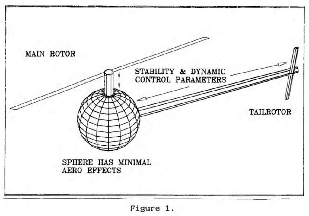 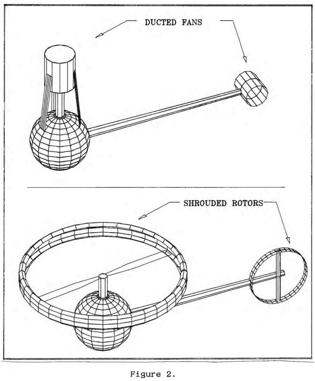 |
 |
  |
|
An
immediate problem is the danger from the rotor. Using a turbojet would only substitute burns for lacerations. A turboshaft powered rotor
would risk both. We propose the lift is provided by a piston driven, ducted fan or shrouded rotor. The potential configurations are shown in
Figure 2. At this point the vehicle is a somewhat large model helicopter with a commensurate level of cost and complexity. It should be noted that low observability will be provided by the use of composites in the structure and radar absorbing material around the engine. It is expected that the RAM and the ducted fan or shrouded rotor will also reduce acoustic observability. Once the vehicle is airborne it must convert itself into a high speed aircraft. Considerable thought and discussion of this requirement resulted in the novel approach depicted in Figures 3 through 6. 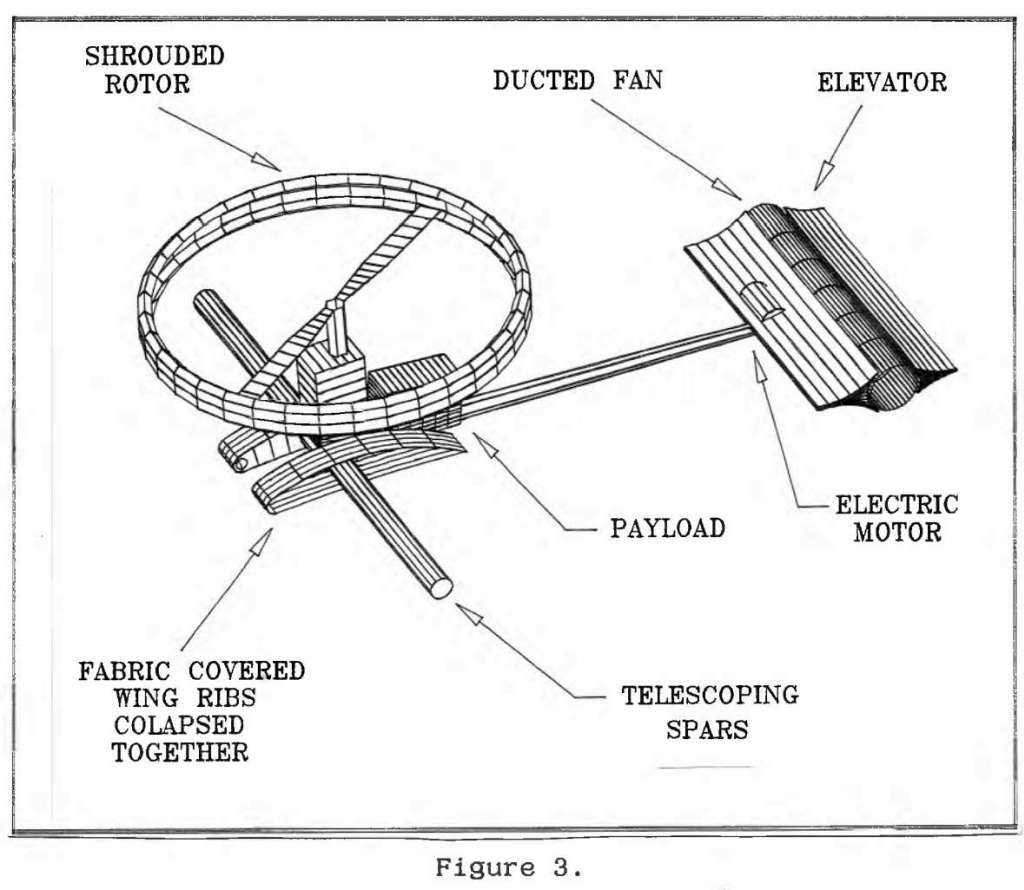 . The craft has a series of fabric covered ribs collapsed together alongside the power-plant. The tail-rotor function is combined with the elevator function of an airplane. The tail-rotor fan is powered by an electric motor to allow for |
 |
  |
|
the most versatile servo-control operation. The particular
configuration shown uses a shrouded rotor and a ducted fan
tail-rotor. There are spars extending from the side of the vehicle. The
payload is carried behind the engine. This configuration provides the
minimum aerodynamic interaction with gusting winds and the rotor
downwash. Figure 4 shows the craft in transition to dash mode. The craft deploys fabric covered wing ribs as its forward velocity increases. This is achieved by extending the ribs along spars which extend out of the fuselage. The overhead rotor tilts forward until it becomes a propeller. It is anticipated that the entire powerplant will tilt with the rotor in order to keep things simple. The electric motor that powers the tailrotor fan is reversible. This allows it to function as a rudder in the dash and loiter modes. It is expected that the wing span will be dynamically controlled in order to maximize transition stability and dash speed as the need may be. 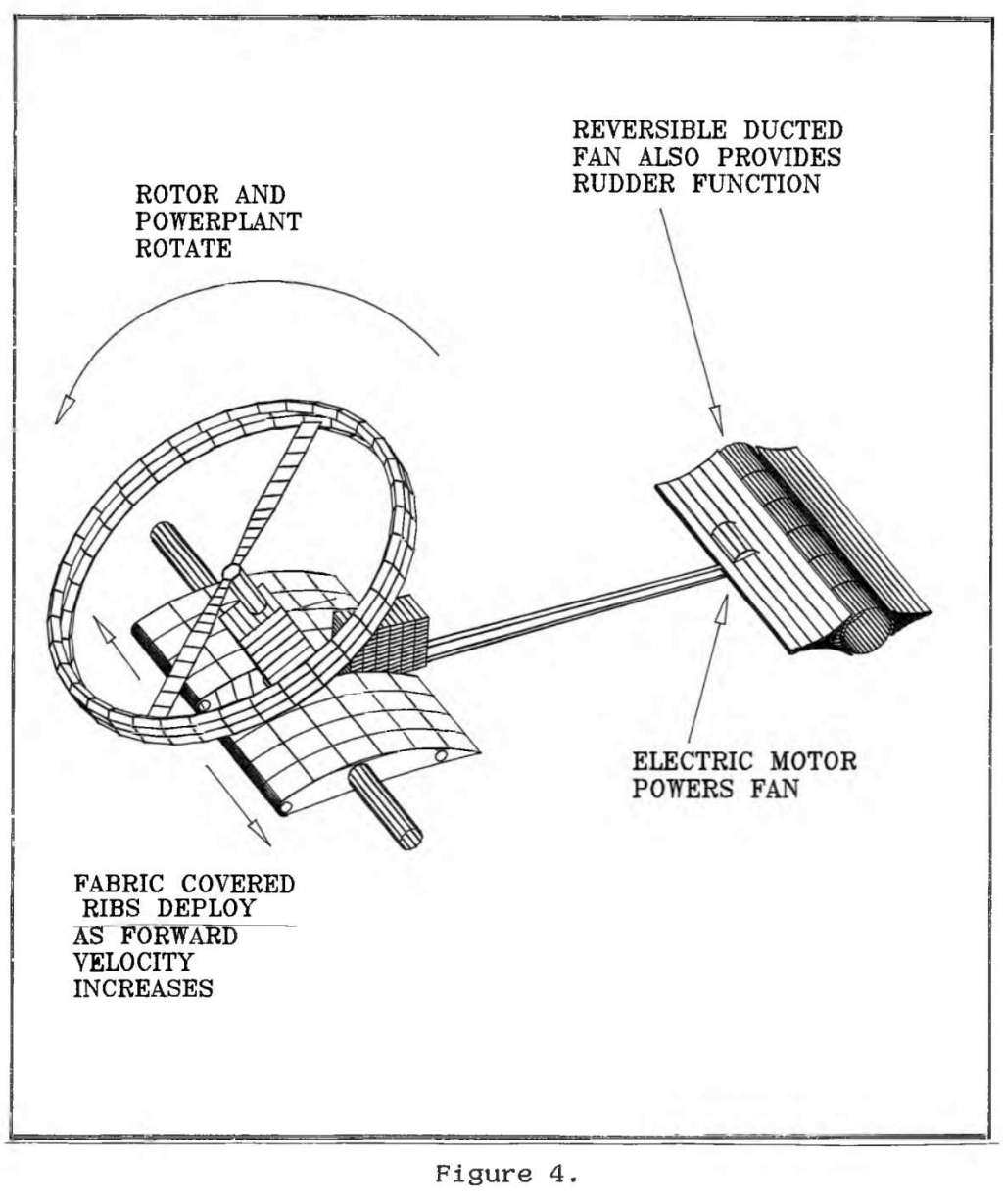 |
 |
  |
|
The vehicle in dash mode is shown in figure 5. The wings have deployed
and the rotor is now functioning as a prop. In this configuration the
craft has the stability and control of a conventional high speed prop driven aircraft. The adjustable pitch of the rotor is used to optimize
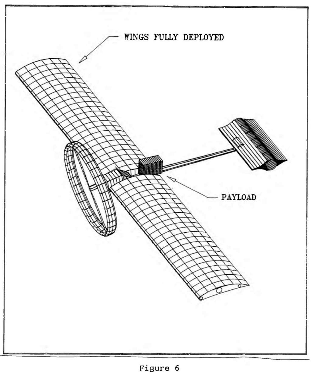
performance. 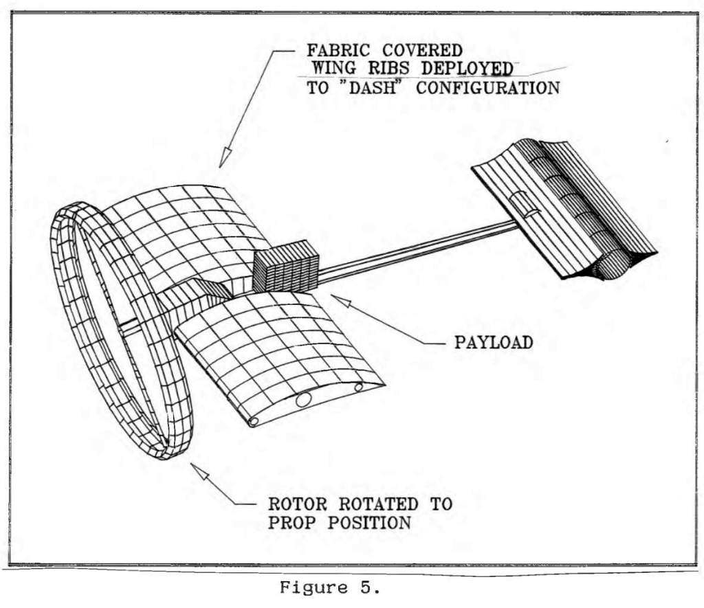 . The requirement for a long loiter time is achieved by further extending the spars as shown in figure 6. The variable pitch rotor is adjusted to minimize fuel consumption. If takeoff and landings need to be very precisely controlled further electronic systems will be added. A laser beam homing system is envisaged. The beam from a laser diode will be projected vertically. On a ship this would result in the beam not moving relative to the ships structure and rigging. The craft will have sensors on its underside to detect the beam. The control algorithm will cause the craft to always maintain the beam at the center of its sensor. The rotor thrust is altered under servo or operator control to effect takeoff and landing. It is anticipated that the transitional time between grounded and dash would be less then a few seconds. |
 |
  |
 . .d. Phase one technical objectives.
|
 |
  |
|
e. Phase I work plan.
|
 |
  |
Proposing activity is working on a kit plane concept vehicle which includes some of the features of the proposed craft. Although this vehicle does not have VTOL capability it is a STOL craft. The aerodynamic analysis and structural analysis is similar. The principal investigator has designed several electronic control systems. These systems are in use in the automotive, industrial and aerospace industries. |
 |
  |
|
g. Relationship with Future Research or Research and Development.
|
 |
  |
|
i. Key Personnel. Paul Rako Mr. Rako is the owner of the proposing firm. He has been an engineering consultant for 10 years. Prior to that, he was a design engineer at ESL division of TRW. He has also been an automotive design engineer for both General motors and Ford. He was educated by General Motors' co-operative program at the General Motors Institute in Flint, Michigan. Mr Rako's firm specializes in the design of complete "turn-key" systems for military, industrial and commercial clients. He has designed both airborne and spaceborne electronic systems. He has an avid interest in both general aviation and RC modeling. Bob Dible is electrical engineer with almost 20 years experience. He has designed several military systems including space systems. He is a champion radio controlled aircraft pilot competing nationally in the Formula 1 class. Bob constructs his own craft and has an excellent intuitive feel for aerodynamics and airworthyness. He has a BSEE from Kansas State University. Andy Masto is a mechanical engineer with a degree in aeronautical engineering from UCLA. He has 20 years experience in design and project management. He is an expert in finite element analysis. j. Facilities/Equipment The proposing firm has a 1500 square foot design and prototype center in Sunnyvale California. Design tools include several computers with both electrical and mechanical software applications. Among these are Autocad, Procad, Orcad, PADS, COSMOS and others. An E-size plotter is used for output. |
 |
  |
|
A
100,000 page component and system library is maintained. There is a complete lab with scopes, spectrum analyzers and other test equipment.
There is no requirements foreseen that would require the purchase of additional equipment. The facilities meet all environmental laws for
the federal, California, Santa Clara County and Sunnyvale governments. These laws encompass airborne emissions, waterborne effluents, external
radiation levels, outdoor noise, solid and bulk waste disposal practices, and the handling and storage of toxic waste. Compliance is
insured through biannual inspections conducted by the Sunnyvale Department of Public Safety. k. Consultants Proposing firm does not anticipate the need for consultants. l. Prior, Current or Pending Support. There is no prior, current or pending support. m. Cost proposal Cost Breakdown Items: 1. Rako Electronics 2. 1161 Tasman Drive P.O. Box 61387 Sunnyvale, CA 94088 3. Work to be done at: As above. 4. Articulated, deployable wing VTOL aircraft. 5. N92-129 Vertical Takeoff and Landing Unmanned Aerial Vehicle for Maritime and Close Combat Applications. 6. Total cost: $ 49,668 7. Direct material costs: a. Purchased parts- $ 0 b. Subcontracted - 0 c. Other (1) Raw Materials 650 (2) Std cmmrcl 0 (3) Interdiv xfer 0 d. Total - 650 |
 |
  |
|
8. Material overhead rate (%22) $793 9. Direct labor a. Engineering 500 hr @ $50/hr =$25,000 Technician 20 hr @ $50/hr = 1,000 Proj manage 130 hr @ $50/hr = 6,500 b. Total 32,500 10.Labor overhead: a. Rate: 35% of 650 hr b. Total labor overhead: $ 11,375 11.Special testing 0 12.Special Equipment 0 13.Travel 0 14.Consultants 0 15. ODC 0 16. G&A a. Rate: 12% b. Total 4,000 17. Royalties: 0 18. Fee/profit 1,000 19. Total Estimate cost: $ 49,668 signed ________________________ Date __________ Paul J. Rako, Owner |
 |
  |
|
21. a. Has any executive agency of the United States
government performed any review of your records in connection
with any other government prime contract or subcontract within the
past 12 months? No b. Will you require the use of any government property in the performance of this proposal? Yes Describe: 1) Drawing of requisite payload volume, outline center of gravity etc. 2) Drawing & specs of applicable piston driven powerplants including conceptual ones for heavy fuel powerplants. c. Do you require government contract financing to perform this proposed contract.? Yes Type: 85% monthly progress payments 15% completion $1000 profit at completion. 22.Type of contract: Firm Fixed Price. |
 |
  |
|
N92-129 TITLE: Vertical Takeoff and Landing Unmanned Aerial Vehicle for Maritime and Close Combat Applications CATEGORY: Advanced Development OBJECTIVE: Develop and demonstrate a safe, high forward speed, vertical takeoff and landing (VTOL) unmanned aerial vehicle for maritime and close combat applications. DESCRIPTION: Next generation UAVs will be required to operate safely and efficiently from available deck space on small surface combatants, and from small clearings or other restricted areas during amphibious close combat operations onshore. The constraints of limited deck space on most surface combatants, with proximity of above-deck rigging and other superstructures, will require a true VTOL class air vehicle for launch and recovery. Support for urban combat and other onshore operations with a mobile landing force also mandates a UAV system which requires minimum landing and takeoff area, with little or no surface preparation before use. Current VTOL UAV designs have inadequate safety features necessary to operate in confined spaces, and most lack the forward transition speed to rapidly reach a desired target area. The air vehicle design must ensure the safety and protection of operating personnel and nearby equipment during launch and recovery. This advanced design must also exceed the forward speed and maneuver capabilities of present VTOL UAVs. Improved forward speed and maneuver capabilities are required to increase survivability in the anticipated hostile anti aircraft combat environment. |
 |
  |
| This forward speed capability must be coupled with appropriate inflight stability, so that the gimbal stabilization requirement for onboard imaging sensors is minimized. The vehicle gross takeoff weight shall not exceed 400 pounds, with a 100 pound payload (control avionics and sensors) and fuel included. The required radius of operation is 100 nautical miles, with a desired maximum on-station loiter time of 8 hours. Operating altitudes range from a hover in ground effect to a minimum in-transit cruise altitude of 10,000 ft AGL. Efficient forward dash speed operation of at least 90 knots TAS is required, with higher speed desire. Design features for reduced vehicle radar and infrared signatures are also desired to further increase expected combat survivability. Phase I: Identify and evaluate innovative concepts that provide a safe, high speed, VTOL unmanned aerial vehicle for maritime and amphibious close combat applications. Develop a plan to mature the design and demonstrate a full scale flight vehicle over the entire projected operating envelope. Phase II: Develop and demonstrate prototype equipment for the air vehicle design proposed under Phase I. |
 |
  |
This post is in these categories:Categories |  |
  |